5G(NR): Xn Based Handover

Introduction:

The basic handover and any type of mobility procedures are same in any type networks, i.e. UE measures the nearby signals and select the some good signals and make the report based on these signal strength and quality and after that sent this report to source cellsource cell take the decision to start handover procedure to best cell that is called Target Cell.  and then target cell completes the Handover procedure.


There are some basic Impotent Pointers for XN Handover:

------------------------------------------------------------------------------

  • Signal strength of both source gNodeB and target gNodeB should be reachable to UE during the handover, because during handover signaling are required with source gNB and target gNB also.
  • Xn-based Handover is very similar X2-based Handover in LTE
  • Xn-based handover is only possible if XnAP interface is established between source and Target gNBs.
  • This type of Handover is only applicable for intra-AMF mobility (with in same AMF ), i.e. Xn handover cannot be used if Source and Target gNB is connected to different AMFs.
  • Xn-based Handover can be both Intra Frequency handover and Inter Frequency handovers.
  • It is possible that source and target gNB can be connected with two different UPFs(user plane functions)
  • Tracking Area code should be same. RRC Re-Registration is requirred after Successful Handover if the Source gNB and the Target gNB belongs to different Tracking Area code (TAC).
  • Xn-based Handover is much faster as Compare to NGAP Handover due to short signaling root and 5G Core involved in only for switch the data path and PDU session.


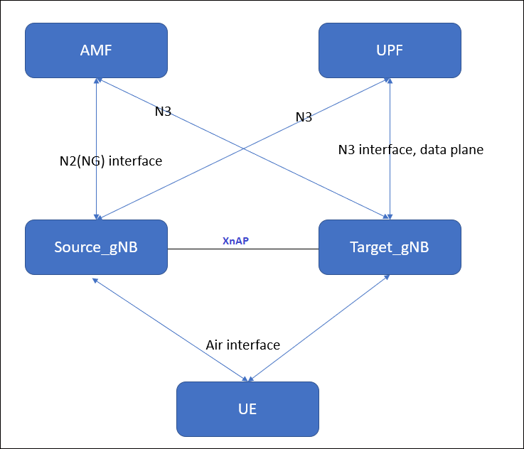
High level setup diagram:

      Both source  gNB  and target gNB is serving by  same AMF and UPF. and source gNB and target gNB should have the active XNAP interface and active NGAP interface with AMF.


Signaling Exchange b/w Source gNB and target gNB is as shown in picture below..


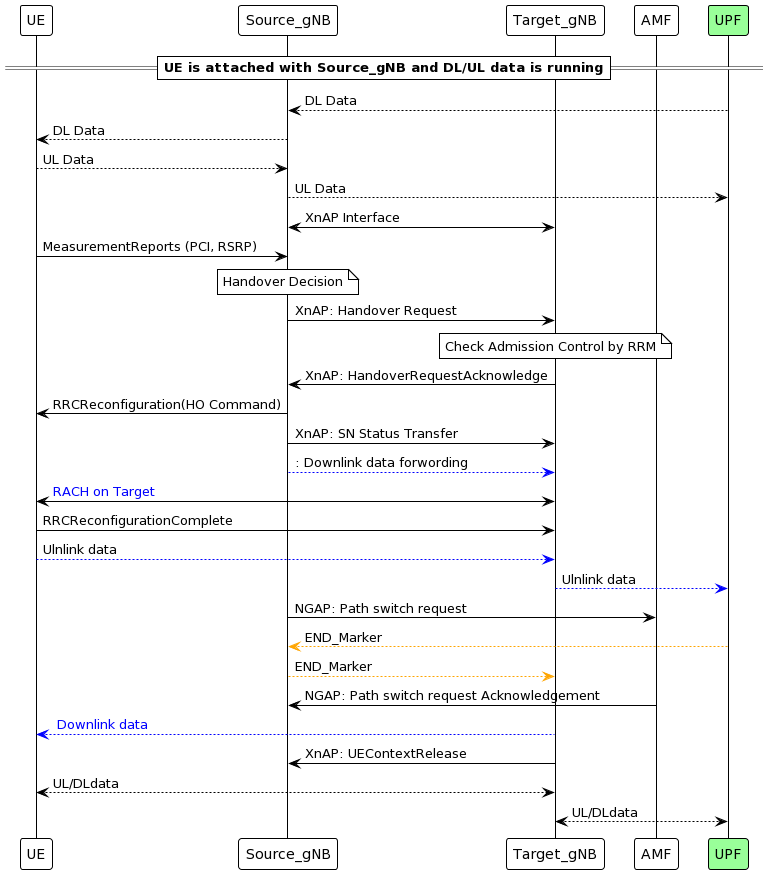
Key Steps in Xn-Based Handover

1. Measurement Reporting

  • UE sends Measurement Report to Source gNB.
  • IEs:
    • MeasResults: Contains signal strength, quality, etc.
    • ReportConfigId: Identifies the reporting configuration.

2. Handover Decision

  • Source gNB decides to initiate handover based on measurements.
  • IEs:
    • TargetCellId: Identifies the target cell.
    • Cause: Reason for handover (e.g., signal degradation).

3. Handover Request (XnAP: Handover Request)

  • Source gNB → Target gNB via Xn interface.
  • IEs:
    • UE Context Information: Includes UE ID, security context.
    • RRC Context: RRC configuration for UE.
    • Bearer Contexts: QoS flows and data bearers.
    • Target Cell ID: Target gNB cell.

4. Handover Request Acknowledge (XnAP)

  • Target gNB → Source gNB.
  • IEs:
    • RRC Configuration: For UE to access target cell.
    • Admitted Bearers: Confirmed bearers for handover.
    • Target to Source Transparent Container: it contains RRC reconfiguration info that goes to UE.

5. Handover Command (RRC: RRCConnectionReconfiguration)

  • Source gNB → UE.
  • IEs:
    • MobilityControlInfo: Target cell info.
    • RadioBearerConfig: Setup for new bearers.
    • MeasurementConfig: New measurement settings.

6. Random Access Procedure

  • UE accesses target cell using contention-free or contention-based RA.
  • IEs:
    • RA-RNTIPreambleIndexTimingAdvance.

7. RRC Reconfiguration Complete

  • UE → Target gNB.
  • IEs:
    • ReconfigComplete: Confirms successful reconfiguration.

8. Path Switch Request (Optional if UPF changes)

  • Target gNB → AMF (if UPF needs update).
  • IEs:
    • UE ContextBearer InfoNew Tunnel Info.

9. Handover Notify (XnAP)

  • Target gNB → Source gNB.
  • IEs:
    • UE IDHandover Status.

10. Resource Release Command

  • Source gNB releases UE resources.
  • IEs:
    • UE IDRelease Cause.

Benefits of Xn-Based Handover

  • Low latency and minimal disruption.
  • No AMF/UPF involvement, reducing signaling overhead.
  • Efficient resource usage and load balancing.


Install Go Lang latest version 1.15.5 in ubuntu

 Download and install

we can install the Go Lang in very easy and simple steps in Linux(Ubuntu)

1. Download Go

2. Install Go

3. Check version of Go

1. Download Go.

Use Curl or wget to download the current binary for Go from the official download page.


sudo wget https://golang.org/dl/go1.15.5.linux-amd64.tar.gz


 If Wget or curl not install, install wget and curl first.


2. Go install.


Extract the archive you downloaded into /usr/local, creating a Go tree in /usr/local/go by below command.

Important: This step will remove a previous installation at /usr/local/go, if any, prior to extracting. Please back up any data before proceeding.

For example, run the following.

sudo tar -C /usr/local -xzf go1.15.5.linux-amd64.tar.gz


Add the go binary path to .bashrc file /etc/profile. Add /usr/local/go/bin to the PATH environment variable.

You can do this by adding the following line to your $HOME/.profile or /etc/profile (for a system-wide installation): 
 
export PATH=$PATH:/usr/local/go/bin

After adding the PATH environment variable, you need to apply changes immediately by running the following command.

source ~/.bashrc

3. Check version of Go

 
Verify that you've installed Go by opening a command prompt and typing the following command: 
 
go version


You can also install go from the snap store too.


sudo snap install --classic --channel=1.15/stable go


Remove Go Lang from the system completely: 

To remove an existing Go installation from your system delete the go directory. This is usually /usr/local/go under Linux.


 sudo rm -rf /usr/local/go 

 sudo nano ~/.bashrc # remove the entry from $PATH 

 source ~/.bashrc

What is Sub-6 GHz[FR1] in 5G?

 In 5G, Sub-6 GHz (often referred to as FR1, or Frequency Range 1) refers to the spectrum of frequencies below 6 GHz that are used for 5G networks. Here’s a detailed overview of Sub-6/FR1 in the context of 5G:

1. What is Sub-6 GHz (FR1) in 5G?

  • Sub-6 GHz, also known as FR1, includes frequencies from 450 MHz up to 6 GHz.
  • It’s the lower-frequency spectrum range used in 5G, as opposed to FR2, which includes millimeter-wave (mmWave) frequencies from 24 GHz to 52 GHz.
  • Sub-6 GHz encompasses frequencies that are widely used in many countries for initial 5G deployments, with bands like 3.5 GHz (also called C-band) being popular for 5G services.

2. Characteristics of Sub-6 GHz (FR1) Spectrum

  • Longer Range: Sub-6 GHz frequencies can cover a larger geographic area, as they experience lower propagation losses than the higher frequencies in the mmWave range.
  • Better Indoor Penetration: Compared to mmWave, Sub-6 GHz signals penetrate buildings and other obstacles more effectively.
  • Moderate Speeds: While Sub-6 offers higher speeds than 4G, its speeds are generally lower than what can be achieved with mmWave. Typical Sub-6 5G speeds range from 100 Mbps up to 1 Gbps, depending on the network conditions and bandwidth.
  • Wide Area Coverage: Due to its range and penetration characteristics, Sub-6 GHz is suitable for providing broader 5G coverage over large urban, suburban, and rural areas.

3. Common Sub-6 GHz Frequency Bands in 5G

  • 3.3 - 3.8 GHz (C-band): One of the primary 5G bands in many regions; balances range, capacity, and speed effectively.
  • 2.5 GHz: Often used in the U.S. and some other markets for 5G.
  • 600 MHz and 700 MHz: Low-band frequencies used for broader 5G coverage, especially in rural and suburban areas.
  • 4.9 GHz: Another option in some countries, although less commonly used than C-band.

4. Advantages of Sub-6 GHz (FR1)

  • Wider Coverage and Better Building Penetration: Makes it suitable for broader coverage across urban, suburban, and rural areas.
  • More Practical for Mobile Use: Compared to mmWave, which is highly directional and short-range, Sub-6 GHz is more practical for typical mobile usage.
  • Fast Deployment: Many operators can deploy Sub-6 5G quickly because it can use spectrum repurposed from other services or new bands allocated by regulators.

5. Limitations of Sub-6 GHz (FR1)

  • Limited Bandwidth: Because it is lower frequency, there is less available bandwidth compared to mmWave, meaning it has lower maximum speeds.
  • Lower Capacity: Sub-6 GHz cannot support as many simultaneous users as mmWave, which may limit performance in very densely populated areas.

6. Use Cases for Sub-6 GHz (FR1)

  • Mobile Broadband: Enhanced mobile broadband (eMBB) services for consumers, such as faster internet and improved video streaming.
  • Smart Cities and IoT: Due to its coverage characteristics, Sub-6 GHz is suitable for IoT deployments across cities and large areas.
  • Urban, Suburban, and Rural Coverage: Provides essential 5G coverage in various environments where mmWave may be impractical.


    For FR2:
    https://5gfundamentals.blogspot.com/2024/11/what-is-mmwave-fr2-in-5g.html

What is ARQ and HARQ?

Both HARQ (Hybrid Automatic Repeat Request) and ARQ (Automatic Repeat Request) are error control mechanisms used in wireless communication to ensure data is received correctly. They mechanism helps in recovery of lost or corrupted packets during transmission.

ARQ (Automatic Repeat Request):

ARQ stands for Automatic Repeat Request. This is the protocol used at data link layer (RLC layer in 5G/4G) . it is an error-control mechanism that is being used in a two-way communication systems.  It is used to achieve reliable data transmission over an unreliable source or service.

 It uses CRC(cyclic redundancy check) to determine, whether the received packet is correct or not. If the packet is received correctly at receiver side, receiver sends ACK to the transmitter, but in case if the packet is not received correctly at receiver side, then receiver send NACK to the transmitter. And then after receiving NACK from receiver side, the transmitter re-transmits the same packet again and so on.

 Concept:

ARQ is a basic error correction method. If a receiver detects an error in a packet (using CRC), it asks the sender to retransmit the entire packet.

How It Works:

  1. Sender transmits a data packet.
  2. Receiver checks for errors using CRC.
  3. If errors are found, receiver sends a NACK (Negative Acknowledgment).
  4. Sender retransmits the same packet.

Types of ARQ:

  • Stop-and-Wait ARQ: Waits for ACK/NACK before sending the next packet.
  • Go-Back-N ARQ: Retransmits from the error point onward.
  • Selective Repeat ARQ: Only retransmits erroneous packets.

Used In:

  • Higher layers like RLC (Radio Link Control) in 5G.


HARQ (Hybrid Automatic Repeat Request)

Concept:

HARQ is a more advanced version of ARQ. It combines error detection with forward error correction (FEC). Instead of resending the same packet, it sends redundant bits to help the receiver decode the original message.

How It Works:

  1. Sender transmits a packet with FEC.
  2. Receiver checks for errors.
  3. If errors are found, receiver sends a NACK.
  4. Sender sends additional redundancy bits (not the same packet).
  5. Receiver combines original and new bits to decode the message.

Key Feature:

  • Uses soft combining (e.g., Chase Combining or Incremental Redundancy).
  • Reduces retransmissions and improves efficiency.

Used In:

  • MAC layer in 5G NR.
  • Works with transport blocks and physical layer transmissions.


HARQ vs ARQ: Key Differences

FeatureARQHARQ
Layer UsedRLCMAC
Retransmission TypeSame packetRedundant bits (soft combining)
Error CorrectionNo (only detection)Yes (FEC + detection)
EfficiencyLowerHigher
LatencyHigherLower
ComplexitySimpleComplex
Use in 5GRLC layerMAC layer