Showing posts with label 5G-NR. Show all posts

5G (NR): DAPS Handover

 Introduction to DAPS Handover 

         In this article, we will discuss the basics of DAPS (Dual Active Protocol Stack) Handover in 5G networks. 

What is DAPS Handover?

         DAPS (Dual Active Protocol Stack) handover is a handover procedure designed to minimize interruption during the transition between cells. In this mechanism, the User Equipment (UE) maintains the source gNB configuration even after receiving the Handover Command and continues using it until the Random Access (RACH) procedure at the target gNB is successfully completed.


 Key Characteristics of DAPS Handover: 

 • UE continues transmission (TX) and reception (RX) on the source cell after receiving the handover request. 

 • UE performs simultaneous reception of user data from both source and target cells. 

 • UE switches uplink (UL) transmission to the target cell after completing the RACH procedure.

 • DAPS reduces handover interruption time to almost 0 ms by maintaining the source radio link while establishing the target radio link. 

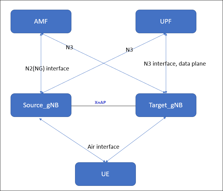
 • DAPS handover is supported over both Xn and NG interfaces. 

 • It can be used for RLC AM (Acknowledged Mode) or RLC UM (Unacknowledged Mode) bearers. 

 • Downlink Data Forwarding is mandatory during a DAPS Handover


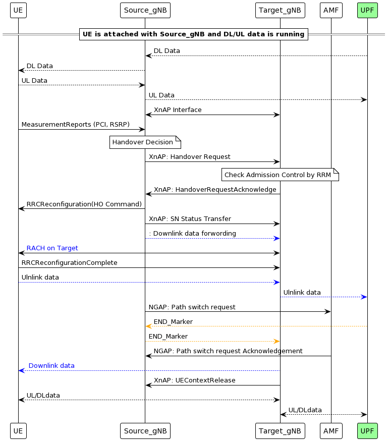
NG-Based DAPS Handover Call Flow:

Step 1: UE sends a Measurement Report to the Source CU, which decides whether to perform a Normal or DAPS Handover.

Step 2: Source CU sends F1AP: UE Context Modification Request to the Source DU with IE gNB-DUConfigurationQuery = TRUE.

Step 3: Source DU responds with UE Context Modification Response including Cell Group Configuration.

 Step 4: Source CU sends NGAP: Handover Required to AMF with DAPS Request Information.

 Step 5: AMF forwards NGAP: Handover Request to Target CU with the same DAPS Request Information.

 Step 6: Target CU sends F1AP: UE Context Setup to Target DU along with Handover Preparation Information.

 Step 7: Target DU responds with UE Context Setup Response including Cell Group Configuration.

Step 8: Source CU sends NGAP: Handover Request Acknowledge to AMF with RRC Reconfiguration and DAPS Response Information.

Step 9: AMF sends NGAP: Handover Command to Source CU with the same RRC Reconfiguration and DAPS details.

Step 10: Source CU forwards F1AP: UE Context Modification to Source DU with RRC Container (HO Command) and DAP_HO_Status = Initiation.

Step 11: UE receives HO Command and performs RACH procedure at Target Cell while still receiving DL data from Source gNB.

Step 12: Source CU sends NGAP: Uplink Early Status Transfer to AMF, which forwards it to Target CU as NGAP: Downlink Early Status Transfer.

 Step 13: After completing RACH, UE sends RRC Reconfiguration Complete to Target Node and switches UL data to Target gNB.

 Step 14: Target CU sends NGAP: Handover Notification to AMF with IE Notify Source NG-RAN Node.

Step 15: AMF sends NGAP: Handover Success to Source CU.

Step 16: Source CU sends F1AP: UE Context Modification to Source DU with TransmissionActionIndication = Stop, stopping DL data transmission.


Step 17: Source CU sends NGAP: Uplink Status Transfer to AMF, which forwards it to Target CU via Downlink Status Transfer.

Step 18: AMF sends NGAP: UE Context Release to Source CU, which clears the UE context and responds.

Step 19: Target CU sends RRC Reconfiguration to UE with daps-SourceRelease and UE responds with RRC Reconfiguration Complete


MSG1 – PRACH in 5G NR


What is MSG1 in 5G?

        MSG-1 is the first message in the Random Acccess Procedure of 5G (NR). It is transmitted by the User Equipment (UE) to the gNodeB (gNB) over the Physical Random Access Channel (PRACH).

MSG1 contains a Random Access Preamble, which is a special signal used by the UE to:

  • Request initial access to the network
  • Re-establish connection after radio link failure
  • Perform handover
  • Synchronize uplink timing

Why is MSG1 Required?

MSG1 is essential because:

  • The UE doesn’t yet have uplink timing aligned with the gNB.
  • It allows the gNB to detect the UEmeasure timing offset, and allocate resources.
  • It initiates communication when the UE is in RRC_IDLERRC_INACTIVE, or during beam failure recovery.

MSG1 Structure (PRACH Preamble)

MSG1 is not a regular/normal message with headers and payload. It’s a waveform generated using Zadoff-Chu sequences. It includes:

FieldExplanation
Preamble IndexIdentifies which preamble UE is using (used for contention resolution).
Sequence FormatLong (839) or Short (139) depending on cell size and deployment scenario.
Subcarrier Spacingit is not constant varies by frequency range (like FR1: 15/30 kHz, FR2: 60/120 kHz).
PRACH Configuration IndexDetermines time/frequency resources for PRACH transmission.
RA-RNTIit is used to identify the UE. it is being used during Random Access Procedure only.
it stands for  "Random Access Radio Network Temporary Identifier"
How MSG1 is Transmitted
  1. UE selects a preamble index and PRACH resource based on configuration from SIB1 or RRC.
  2. UE transmits the PRACH waveform using selected format and power.
  3. The transmission is blind—UE doesn’t know if gNB received it.


What Happens at gNB After Receiving MSG1?

Once gNB receives MSG1:

  1. It detects the preamble and estimates timing offset.
  2. It sends MSG2 (Random Access Response) via PDCCH and PDSCH.
  3. MSG2 includes:
    • Timing Advance
    • Temporary C-RNTI
    • Uplink grant for MSG3

If multiple UEs send the same preamble (contention-based access), gNB resolves it in later steps (MSG4).


MSG1 in the Full Random Access Procedure


UE                                                                    gNB
│                                                                          │
├── MSG1: PRACH Preamble   ─────▶│  (Initial access)
│◀── MSG2: RAR (Timing, Grant)    ── ┤
├── MSG3: RRC Setup Request  ────▶│
│◀── MSG4: Contention Resolution  ──┤

SRS(Sounding reference signal) in NR:

 SRS(Sounding reference signal) in NR:

       In the world of 5G New Radio (NR), efficient and accurate uplink channel estimation is crucial for maintaining high data rates and reliable connectivity. One of the key tools used for this purpose is the Sounding Reference Signal (SRS).


What is SRS?

          SRS is a type of uplink reference signal transmitted by the User Equipment (UE) to help the gNodeB (5G base station) assess the quality of the uplink channel. Unlike other reference signals that are tied to data transmission, SRS is often sent independently of data, purely for the purpose of channel sounding.


Why is SRS Important in 5G?

5G networks operate across a wide range of frequencies, including millimeter wave bands, where channel conditions can vary rapidly. SRS helps the network:

  • Estimate uplink channel quality across different frequency resources.
  • Support beamforming and massive MIMO by providing spatial channel information.
  • Enable frequency-selective scheduling, allowing the network to assign resources based on real-time channel conditions.
  • Assist in mobility management, especially in scenarios involving handovers or dual connectivity.

How Does SRS Work?

The gNodeB configures the UE to transmit SRS periodically or on-demand. These signals are sent over specific resource blocks and are designed to be orthogonal to other uplink transmissions to avoid interference.

Key aspects of SRS configuration include:

  • Bandwidth and frequency hopping: SRS can span wide bandwidths and hop across frequencies to provide a comprehensive channel view.
  • Time-domain configuration: SRS can be scheduled at regular intervals or triggered dynamically.
  • Antenna port mapping: In MIMO setups, SRS can be transmitted from multiple antenna ports to help the gNodeB understand spatial characteristics.

1. SRS Triggering Mechanisms

SRS transmission can be initiated in two main ways:

  • Periodic Triggering: The UE sends SRS at regular intervals based on a predefined schedule.
  • Aperiodic Triggering: The gNodeB can request SRS on-demand via Downlink Control Information (DCI), allowing dynamic channel sounding when needed.

This flexibility helps balance overhead and responsiveness.


2. Time-Domain Configuration

SRS can be configured to occur in specific time slots or symbols. Key parameters include:

  • SRS Periodicity: Defines how often the UE should transmit SRS (e.g., every 20 ms, 40 ms).
  • Offset: Determines the starting point of the periodic transmission within a frame.
  • Duration: Specifies how many symbols are used for SRS in a slot.

This allows operators to optimize SRS timing based on traffic load and mobility.


3. Frequency-Domain Configuration

SRS can be transmitted over a wide or narrow frequency range. Important aspects include:

  • Bandwidth Configuration: SRS can span multiple resource blocks (RBs), enabling wideband channel estimation.
  • Frequency Hopping: SRS can hop across different frequency locations to provide a broader view of the channel.
  • Comb Size: Determines the spacing between SRS tones, affecting resolution and overhead.

These settings help the gNodeB assess frequency-selective fading and optimize resource allocation.


4. Spatial Configuration

In MIMO systems, SRS can be transmitted from multiple antenna ports. This supports:

  • Uplink Beamforming: By analyzing SRS from different spatial directions, the gNodeB can select optimal beams.
  • Channel Reciprocity: In TDD systems, uplink SRS can help infer downlink channel conditions.

This is especially useful in massive MIMO deployments.


5. Group and Sequence Configuration

SRS uses specific sequences and cyclic shifts to maintain orthogonality between UEs:

  • Sequence Group and ID: Defines the base sequence used for SRS.
  • Cyclic Shift: Allows multiple UEs to transmit SRS simultaneously without interference.

This ensures scalability and efficient multi-user support.


6. SRS Resource Configuration

The gNodeB defines SRS resources using RRC signaling. Each resource includes:

  • Resource ID
  • Time and frequency allocation
  • Antenna port mapping
  • Transmission comb and sequence parameters

These configurations are managed via the SRS-Config structure in the RRC protocol.


SRS Configuration Summary Table

ParameterDescription
Trigger TypePeriodic or Aperiodic (on-demand via DCI)
PeriodicityDefines how often SRS is transmitted (e.g., every 20 ms, 40 ms)
OffsetTime offset within the frame for periodic SRS
DurationNumber of OFDM symbols used for SRS in a slot
Bandwidth ConfigurationNumber of resource blocks (RBs) allocated for SRS
Frequency HoppingEnables SRS transmission across different frequency locations
Comb SizeSpacing between SRS tones (e.g., 2, 4, 8)
Antenna PortsNumber of antenna ports used for SRS (supports MIMO and beamforming)
Sequence Group & IDDefines the base sequence used for SRS
Cyclic ShiftAllows multiple UEs to transmit SRS simultaneously without interference
SRS Resource IDUnique identifier for each configured SRS resource

DCI_Format 0_0 Decoder:

DCI Format 0_0:

This is used for the scheduling of PUSCH in a single cell and it is shared by gNB to UE in DL direction. UE is required to decode the UL grant on PDCCH, so that the UE can transmit PUSCH on UL Slot in Uplink. DCI 0_0 is mainly used for common search space signaling and UL Grant.

Field of DCI 0_0:

Add program

Decoder


Number of BWP RBs :

UL-DCI HexValue      :

Binary value :

DCI Fields No of bits Bits Decimal value
Identifier for DCI formats 1
Frequency domain resource assignment  
Time domain resource assignment 4
Frequency hopping flag 1
Modulation and coding scheme 5
New data indicator 1
Redundancy version 2
HARQ process number 4
TPC command for scheduled PUSCH 2
Padding Bits x
UL/SUL indicator x


5G(NR): Xn Based Handover

Introduction:

The basic handover and any type of mobility procedures are same in any type networks, i.e. UE measures the nearby signals and select the some good signals and make the report based on these signal strength and quality and after that sent this report to source cellsource cell take the decision to start handover procedure to best cell that is called Target Cell.  and then target cell completes the Handover procedure.


There are some basic Impotent Pointers for XN Handover:

------------------------------------------------------------------------------

  • Signal strength of both source gNodeB and target gNodeB should be reachable to UE during the handover, because during handover signaling are required with source gNB and target gNB also.
  • Xn-based Handover is very similar X2-based Handover in LTE
  • Xn-based handover is only possible if XnAP interface is established between source and Target gNBs.
  • This type of Handover is only applicable for intra-AMF mobility (with in same AMF ), i.e. Xn handover cannot be used if Source and Target gNB is connected to different AMFs.
  • Xn-based Handover can be both Intra Frequency handover and Inter Frequency handovers.
  • It is possible that source and target gNB can be connected with two different UPFs(user plane functions)
  • Tracking Area code should be same. RRC Re-Registration is requirred after Successful Handover if the Source gNB and the Target gNB belongs to different Tracking Area code (TAC).
  • Xn-based Handover is much faster as Compare to NGAP Handover due to short signaling root and 5G Core involved in only for switch the data path and PDU session.


High level setup diagram:

      Both source  gNB  and target gNB is serving by  same AMF and UPF. and source gNB and target gNB should have the active XNAP interface and active NGAP interface with AMF.


Signaling Exchange b/w Source gNB and target gNB is as shown in picture below..


Key Steps in Xn-Based Handover

1. Measurement Reporting

  • UE sends Measurement Report to Source gNB.
  • IEs:
    • MeasResults: Contains signal strength, quality, etc.
    • ReportConfigId: Identifies the reporting configuration.

2. Handover Decision

  • Source gNB decides to initiate handover based on measurements.
  • IEs:
    • TargetCellId: Identifies the target cell.
    • Cause: Reason for handover (e.g., signal degradation).

3. Handover Request (XnAP: Handover Request)

  • Source gNB → Target gNB via Xn interface.
  • IEs:
    • UE Context Information: Includes UE ID, security context.
    • RRC Context: RRC configuration for UE.
    • Bearer Contexts: QoS flows and data bearers.
    • Target Cell ID: Target gNB cell.

4. Handover Request Acknowledge (XnAP)

  • Target gNB → Source gNB.
  • IEs:
    • RRC Configuration: For UE to access target cell.
    • Admitted Bearers: Confirmed bearers for handover.
    • Target to Source Transparent Container: it contains RRC reconfiguration info that goes to UE.

5. Handover Command (RRC: RRCConnectionReconfiguration)

  • Source gNB → UE.
  • IEs:
    • MobilityControlInfo: Target cell info.
    • RadioBearerConfig: Setup for new bearers.
    • MeasurementConfig: New measurement settings.

6. Random Access Procedure

  • UE accesses target cell using contention-free or contention-based RA.
  • IEs:
    • RA-RNTIPreambleIndexTimingAdvance.

7. RRC Reconfiguration Complete

  • UE → Target gNB.
  • IEs:
    • ReconfigComplete: Confirms successful reconfiguration.

8. Path Switch Request (Optional if UPF changes)

  • Target gNB → AMF (if UPF needs update).
  • IEs:
    • UE ContextBearer InfoNew Tunnel Info.

9. Handover Notify (XnAP)

  • Target gNB → Source gNB.
  • IEs:
    • UE IDHandover Status.

10. Resource Release Command

  • Source gNB releases UE resources.
  • IEs:
    • UE IDRelease Cause.

Benefits of Xn-Based Handover

  • Low latency and minimal disruption.
  • No AMF/UPF involvement, reducing signaling overhead.
  • Efficient resource usage and load balancing.


What is Sub-6 GHz[FR1] in 5G?

 In 5G, Sub-6 GHz (often referred to as FR1, or Frequency Range 1) refers to the spectrum of frequencies below 6 GHz that are used for 5G networks. Here’s a detailed overview of Sub-6/FR1 in the context of 5G:

1. What is Sub-6 GHz (FR1) in 5G?

  • Sub-6 GHz, also known as FR1, includes frequencies from 450 MHz up to 6 GHz.
  • It’s the lower-frequency spectrum range used in 5G, as opposed to FR2, which includes millimeter-wave (mmWave) frequencies from 24 GHz to 52 GHz.
  • Sub-6 GHz encompasses frequencies that are widely used in many countries for initial 5G deployments, with bands like 3.5 GHz (also called C-band) being popular for 5G services.

2. Characteristics of Sub-6 GHz (FR1) Spectrum

  • Longer Range: Sub-6 GHz frequencies can cover a larger geographic area, as they experience lower propagation losses than the higher frequencies in the mmWave range.
  • Better Indoor Penetration: Compared to mmWave, Sub-6 GHz signals penetrate buildings and other obstacles more effectively.
  • Moderate Speeds: While Sub-6 offers higher speeds than 4G, its speeds are generally lower than what can be achieved with mmWave. Typical Sub-6 5G speeds range from 100 Mbps up to 1 Gbps, depending on the network conditions and bandwidth.
  • Wide Area Coverage: Due to its range and penetration characteristics, Sub-6 GHz is suitable for providing broader 5G coverage over large urban, suburban, and rural areas.

3. Common Sub-6 GHz Frequency Bands in 5G

  • 3.3 - 3.8 GHz (C-band): One of the primary 5G bands in many regions; balances range, capacity, and speed effectively.
  • 2.5 GHz: Often used in the U.S. and some other markets for 5G.
  • 600 MHz and 700 MHz: Low-band frequencies used for broader 5G coverage, especially in rural and suburban areas.
  • 4.9 GHz: Another option in some countries, although less commonly used than C-band.

4. Advantages of Sub-6 GHz (FR1)

  • Wider Coverage and Better Building Penetration: Makes it suitable for broader coverage across urban, suburban, and rural areas.
  • More Practical for Mobile Use: Compared to mmWave, which is highly directional and short-range, Sub-6 GHz is more practical for typical mobile usage.
  • Fast Deployment: Many operators can deploy Sub-6 5G quickly because it can use spectrum repurposed from other services or new bands allocated by regulators.

5. Limitations of Sub-6 GHz (FR1)

  • Limited Bandwidth: Because it is lower frequency, there is less available bandwidth compared to mmWave, meaning it has lower maximum speeds.
  • Lower Capacity: Sub-6 GHz cannot support as many simultaneous users as mmWave, which may limit performance in very densely populated areas.

6. Use Cases for Sub-6 GHz (FR1)

  • Mobile Broadband: Enhanced mobile broadband (eMBB) services for consumers, such as faster internet and improved video streaming.
  • Smart Cities and IoT: Due to its coverage characteristics, Sub-6 GHz is suitable for IoT deployments across cities and large areas.
  • Urban, Suburban, and Rural Coverage: Provides essential 5G coverage in various environments where mmWave may be impractical.


    For FR2:
    https://5gfundamentals.blogspot.com/2024/11/what-is-mmwave-fr2-in-5g.html

What is ARQ and HARQ?

Both HARQ (Hybrid Automatic Repeat Request) and ARQ (Automatic Repeat Request) are error control mechanisms used in wireless communication to ensure data is received correctly. They mechanism helps in recovery of lost or corrupted packets during transmission.

ARQ (Automatic Repeat Request):

ARQ stands for Automatic Repeat Request. This is the protocol used at data link layer (RLC layer in 5G/4G) . it is an error-control mechanism that is being used in a two-way communication systems.  It is used to achieve reliable data transmission over an unreliable source or service.

 It uses CRC(cyclic redundancy check) to determine, whether the received packet is correct or not. If the packet is received correctly at receiver side, receiver sends ACK to the transmitter, but in case if the packet is not received correctly at receiver side, then receiver send NACK to the transmitter. And then after receiving NACK from receiver side, the transmitter re-transmits the same packet again and so on.

 Concept:

ARQ is a basic error correction method. If a receiver detects an error in a packet (using CRC), it asks the sender to retransmit the entire packet.

How It Works:

  1. Sender transmits a data packet.
  2. Receiver checks for errors using CRC.
  3. If errors are found, receiver sends a NACK (Negative Acknowledgment).
  4. Sender retransmits the same packet.

Types of ARQ:

  • Stop-and-Wait ARQ: Waits for ACK/NACK before sending the next packet.
  • Go-Back-N ARQ: Retransmits from the error point onward.
  • Selective Repeat ARQ: Only retransmits erroneous packets.

Used In:

  • Higher layers like RLC (Radio Link Control) in 5G.


HARQ (Hybrid Automatic Repeat Request)

Concept:

HARQ is a more advanced version of ARQ. It combines error detection with forward error correction (FEC). Instead of resending the same packet, it sends redundant bits to help the receiver decode the original message.

How It Works:

  1. Sender transmits a packet with FEC.
  2. Receiver checks for errors.
  3. If errors are found, receiver sends a NACK.
  4. Sender sends additional redundancy bits (not the same packet).
  5. Receiver combines original and new bits to decode the message.

Key Feature:

  • Uses soft combining (e.g., Chase Combining or Incremental Redundancy).
  • Reduces retransmissions and improves efficiency.

Used In:

  • MAC layer in 5G NR.
  • Works with transport blocks and physical layer transmissions.


HARQ vs ARQ: Key Differences

FeatureARQHARQ
Layer UsedRLCMAC
Retransmission TypeSame packetRedundant bits (soft combining)
Error CorrectionNo (only detection)Yes (FEC + detection)
EfficiencyLowerHigher
LatencyHigherLower
ComplexitySimpleComplex
Use in 5GRLC layerMAC layer

Numerology in 5G

 Numerology in 5G refers to the configuration of key physical layer parameters, primarily based on the subcarrier spacing (SCS), which is fundamental to the structure of the 5G New Radio (NR) interface. It allows for greater flexibility to meet diverse use cases in 5G, such as enhanced Mobile Broadband (eMBB), ultra-reliable low latency communications (URLLC), and massive Machine Type Communications (mMTC).

Key Concepts in 5G Numerology

  1. Subcarrier Spacing (SCS)
    In 5G, the subcarrier spacing is no longer fixed as in LTE (15 kHz). Instead, multiple subcarrier spacings are supported:

    • SCS=15×2μkHz\text{SCS} = 15 \times 2^\mu \, \text{kHz}, where μ\mu is the numerology index (0, 1, 2, etc.).
    Numerology (μ)Subcarrier Spacing (kHz)
    015
    130
    260
    3120
    4240
    • Higher SCS is used for higher frequency bands and low-latency applications.
    • Lower SCS is suitable for lower frequency bands and wider coverage.
  2. Slot Duration
    The slot duration changes inversely with the SCS:

    Slot Duration=1ms2μ\text{Slot Duration} = \frac{1 \, \text{ms}}{2^\mu}
    • At μ=0\mu = 0 (15 kHz), slot duration is 1 ms.
    • At μ=2\mu = 2 (60 kHz), slot duration is 0.25 ms.
  3. Bandwidth Scaling
    The overall bandwidth and Resource Block (RB) size depend on the numerology:

    • Higher numerology (larger SCS) requires more frequency bandwidth for a given number of subcarriers.
    • For example, one RB (12 subcarriers) at 15 kHz spans 180 kHz, while at 30 kHz, it spans 360 kHz.
  4. Flexible Frame Structure
    5G supports variable frame and subframe durations:

    • A standard frame is 10 ms, subdivided into 10 subframes of 1 ms.
    • The number of slots per subframe depends on the numerology. For example, μ=1\mu = 1 results in 2 slots per subframe.
  5. Applications of Numerology

    • Low SCS (15 kHz): Suitable for wide-area coverage (e.g., rural environments).
    • Medium SCS (30-60 kHz): Ideal for urban eMBB and IoT deployments.
    • High SCS (120-240 kHz): Essential for mmWave bands and low-latency services.

Benefits of 5G Numerology

  • Flexibility: Supports a wide range of services and frequencies.
  • Efficiency: Allows better optimization of spectrum use and latency.
  • Scalability: Adapts to diverse deployment scenarios, from dense urban areas to rural coverage.