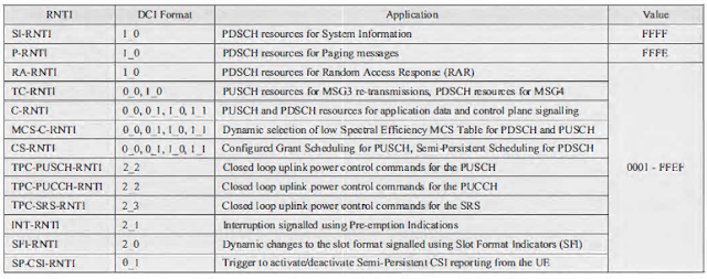
5G(NR)- Radio Network Temporary Identifier (RNTI)

 Radio Network Temporary Identifier (RNTI):

Radio Network Temporary Identifiers (RNTl) are applicable within the Radio Access Network. They are allocated by the Base Station and are subsequently stored by both the Base Station and UE. They are used to address either an individual UE, a group of UE or all UE. For example, the C-RNTI can be used to address an individual UE, whereas an INT-RNTI can be used to address a group of UEs and the SI-RNTI can be used to address all UE.

A UE is addressed by using the RNTI to scramble the CRC bits which are attached to the PDCCH OCI payload, i.e. an RNTI is used to address the UE on the PDCCH. The PDCCH can then be used to provide uplink and downlink resource allocations, power control commands, pre-emption indications, Slot Format changes and System Information update indications.

The set of RNTI is presented in below table . All RNTI have a length of  16 bits.

The Sl-RNTI is used to scramble the CRC bits belonging to DCI Format 1_0 when allocating PDSCH resources for the transmission of System Information. 3GPP has standardised a single SI-RNTI value which is used by all UE.

The P-RNTI is used to scramble the CRC bits belonging to DCI Format 1_0 when allocating PDSCH resources for the transmission of Paging messages, or when using the PDCCH to encapsulate a 'Short Message'. A 'Short Message' can be used to indicate that System Information content has changed and needs to be re-acquired. It can also be used to indicate an Earthquake and Tsunami Warnings.

System (ETWS) primary notification on SIB6, or an ETWS secondary notification on SIB9, or a Commercial Mobile Alert System(CMAS) notification on SIB8. 3GPP has standardised a single IP-RNTI value which is used by all UE.

RNTI as per 3GPP 38.321 Table 7.1-2


The RA-RNTI is used during the Random Access procedure when allocating PDSCH resources for the Random Access Response(MSG2). There is a one-to-one mapping between the RA-RNTI and the time-frequency resource used by the UE when transmitting the Random Access Preamble. This means that all UE using the same Random Access occasion will share the same RA-RNTI and the same PDCCH transmission. The content of the PDSCH differentiates between the set of UE using the Random Access Preamble Identity (RAPID) within the MAC sub-header.

The Temporary C-RNTl (TC-RNTI) is allocated during tbc Random Access procedure within the Random Access Response (MSG2).It is subsequently used to address the UE when allocating PUSCH resources for MSG3 re-transmissions. It is not necessary to use the TC-RNTI when allocating resources for the initial MSG3 transmission because that resource allocation is included within MSG2(rather than within a PDCCH transmission). The TC-RNTI is also used when allocating PDSCH resources for MSG4

The Cell RNTI (C-RNTI) is set equal to the TC-RNTI after successful Random Access contention resolution. The C-RNTI is changed whenever a UE completes a handover towards a new cell. The C-RNTI is used to address the UE when allocating PDSCH or PUSCH resources to that UE.


I-RNTI

The Inactive RNTI (1-RNTI) is applicable to the RRC Inactive State. In contrast to other RNTI, the I-RNTI is not used to scramble the CRC bits belonging to the PDCCH payload. instead, the 1-RNTI is used to address the UE within RRC signalling messages.

An I-RNTI can be allocated to a UE within an RRC Release message when moving the UE from RRC Connected to RRC Inactive.

There are two variants of the 1-RNTI:

  • A full I-RNTI which has a length of 40 bits. This variant can be included within an RRCResumeRequest1 message which has a size of 64 bits. This is relatively large for a MSG3 transmission, so there is a risk that uplink coverage may be compromised.
  • A short I-RNTI which has a length of 24 bits. This variant can be included within an RRCResumeReqest message which has a size of 48 bits. This is the normal size for MSG3 .

The useFullResumeID flag within SIB-1 instructs the UE to use either the full or short I-RNTI when resuming a connection, that means. this flag instructs the UE to send either an RRCResumeRequest message or an RRCResumeRequestl message.

The I-RNTI can be used to address a UE within an RRC Paging message when the UE is RRC Inactive state.

5G(NR): Scheduling Request


5G(NR): Scheduling Request:

This Blog will explain about the NR scheduling request mechanism which is applicable between UE and gNodeB. 

The Scheduling Request is triggered when UE is in uplink sync with gNodeB and It is not having and up-link (PUSCH/PUCCH) resource allocated for transmission of  new user plane or control plane data. 

 
The Scheduling Request (SR) is used for requesting UL-SCH resources( up-link grant ) for new transmission on PUCCH channel. 
 
Network (gNodeB) replies the UE with uplink grant in DCI 0_0 or DCI 0_1 messages on PDCCH channel.  


Configuration:
 
RRC connection setup or RRC reconfiguration request are used to configure the scheduling request related parameters. 
 
 
-MAC is controling the SR and the IE MAC-CellGroupConfig is used to configure MAC parameters for a cell group.
 

MAC-CellGroupConfig ::= SEQUENCE {  

      drx-Config SetupRelease { DRX-Config } OPTIONAL, -- Need M 

      schedulingRequestConfig

       bsr-Config

       tag-Config     

       phr-Config

       skipUplinkTxDynamic BOOLEAN,  

... }

-The IE SchedulingRequestConfig is used to configure the parameters, for the dedicated scheduling request (SR) resources. 


SchedulingRequestConfig ::= SEQUENCE {

    schedulingRequestToAddModList       SEQUENCE

                                               SchedulingRequestToAddMod  OPTIONA,

    schedulingRequestToReleaseList      SEQUENCE

                                               SchedulingRequestId  OPTIONAL -- Need N

}


SchedulingRequestToAddMod ::= SEQUENCE {

    schedulingRequestId                 SchedulingRequestId,

    sr-ProhibitTimer                    ENUMERATED {ms1, ms2, ms4, ms8, ms16,

                                                    ms32, ms64, ms128}

    sr-TransMax                         ENUMERATED {n4, n8, n16, n32, n64,

                                                    spare3, spare2, spare1}

}


- The IE "SchedulingRequestId" is used to identify a Scheduling Request instance in the MAC layer.


 SchedulingRequestId ::= INTEGER (0..7)


Each SR configuration corresponds to one or more logical channels. Each logical channel may be mapped to zero or one SR configuration, which is configured by RRC. 

 RRC configures the following parameters for the scheduling request procedure:  

- sr-ProhibitTimer (per SR configuration);  

- sr-TransMax (per SR configuration).


 SR will NOT be transmitted if:

  1. SR opportunity falls in measurement gap interval or
  2. another SR-Prohibit timer is running or
  3. DL PDCCH with UL resources is received.


5G(NR): MAC Control Elements

 MAC Control Elements:

- As we know that RRC and NAS messages functions are used to exchange the signalings between UE and gNodeB, But there are several communication path at MAC layer. so there are special MAC structures that carries special control information. These special MAC structure carrying the control information is called 'MAC CE', which means 'MAC Control Element'.
-
 -MAC CE works between UE(MAC) and gNodeB(MAC) for FAST Signaling Communication Exchange without  involving upper layers. 

- It is sent as a part of MAC PDUIt  always placed before any MAC SDUs LCID field denotes MAC CE Types.


There are several Type of MAC-CE, MAC CE List specified in 38.321 v15.3:


LCID VALUES FOR DL-SCH 

LCID Table for DL-SCH

 LCID values for UL-SCH channel.

LCID Table for UL-SCH


MAC-CE and reference:


MAC CE

Reference

Buffer Status Report

38.321 - 6.1.3.1

C-RNTI

38.321 - 6.1.3.2

UE Contention Resolution Identity

38.321 - 6.1.3.3

Timing Advance Command

38.321 - 6.1.3.4

DRX Command

38.321 - 6.1.3.5

Long DRX Command

38.321 - 6.1.3.6

Configured Grant Confirmation

38.321 - 6.1.3.7

Single Entry PHR

38.321 - 6.1.3.8

Multiple Entry PHR

38.321 - 6.1.3.9

SCell Activation/Deactivation

38.321 - 6.1.3.10

Duplication Activation/Deactivation

38.321 - 6.1.3.11

SP CSI-RS / CSI-IM Resource Set Activation/Deactivation MAC CE

38.321 - 6.1.3.12

Aperiodic CSI Trigger State Subselection MAC CE

38.321 - 6.1.3.13

TCI States Activation/Deactivation for UE-specific PDSCH MAC CE

38.321 - 6.1.3.14

TCI State Indication for UE-specific PDCCH MAC CE

38.321 - 6.1.3.15

SP CSI reporting on PUCCH Activation/Deactivation MAC CE

38.321 - 6.1.3.16

SP SRS Activation/Deactivation MAC CE

38.321 - 6.1.3.17

PUCCH spatial relation Activation/Deactivation MAC CE

38.321 - 6.1.3.18

SP ZP CSI-RS Resource Set Activation/Deactivation MAC CE

38.321 - 6.1.3.19

Recommended bit rate MAC CE

38.321 - 6.1.3.20


MAC CE Header:


- below are the MAC Control Elements of Buffer Status Report:


1- Short BSR and Truncated BSR format :

2- Long BSR format: 


Format of C-RNTI MAC Control Element: 

C-RNTI MAC control element fields

UE Contention Resolution Identity MAC Control Element :

UE Contention Resolution Identity MAC control element IEs
- it has fixed 48-bit size
- UE Contentions Resolution Identity: This field contains uplink CCCH SDU.

3C : MAC subheader - Contention Resolution:
R = 0
R = 0
E = 1
LCID = 11100 = Contention Resolution.


Timing Advance Command MAC control element
1- Timing Advance Command is of 6 bits in length. TA (0, 1, 2… 63)
Power Headroom MAC Control Element : 


Power Headroom MAC control element
Activation/De-activation MAC Control Element : 
- The Ci field is set to '0' to indicate that the SCell with SCellIndex i shall be de-activated.


Activation/De-activation MAC control elements

Padding MAC Sub-Header:


1F : MAC subheader - Padding
R = 0
R = 0
E = 0
LCID = 11111 = Padding